
Asset Management – System Architecture
System Architecture
The Figure below shows the architecture of the Big Data platform used by the RTLS.
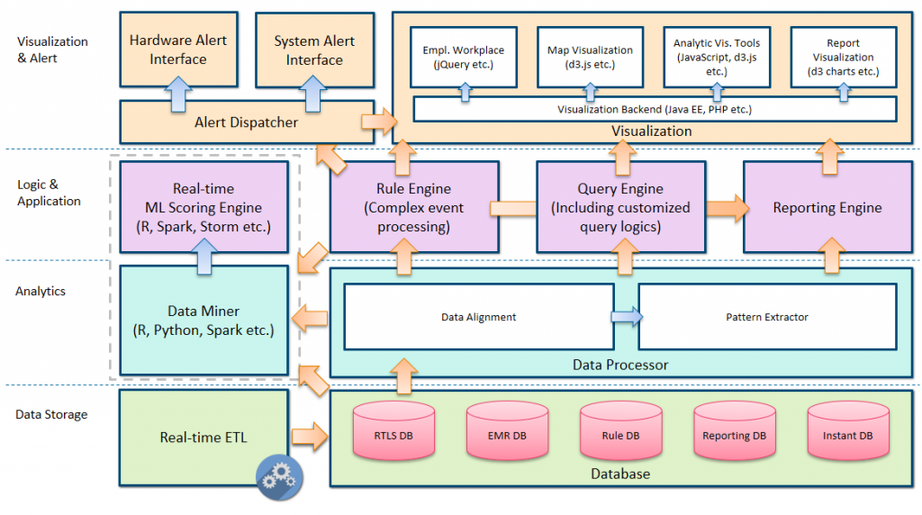
Figure 1 – Architecture of RTLS platform
The system consists of 4 levels. The basic level is the data storage. This level does job not only for data storage but also for the data ETL (extract, transform and load) in real-time. The data from different sources will be stored in separate databases.
On top of the data storage is analytics, which includes a Data Miner component, which does machine learning based predictions based on the database. Another component is the data processor, which does two jobs: align the data with different sources, for example, merge two data sources according to timestamp and entity ID. Pattern extractor, which extracts patterns from the merged data.
One level above the analytics is the logic & application level. There are 4 components in this level. First is the real-time ML (machine learning) scoring engine. There is an interface between this scoring engine with the data miner component from the level below. The models produced in the data miner will be deployed onto the scoring engine for real-time scoring. The rule engine is responsible for detecting interesting & risky patterns. The query engine can take queries from the user interface and translate the query into SQL, execute in the database and return data results. The reporting engine can run predefined reports given customized parameters.
The top level is the visualization & alert level. This is a level that directly interacts with users. It consists of two basic parts. The first part is the alert dispatcher. It can dispatch the alerts generated from the rule engine to specified users in specified channels. The visualization component is implemented by a java web server as back-end an HTML 5 based front-end. It visualizes the current status information and analytic results to the users.
Data Flow & Interoperability of services
Figure 2 below describes how data flows between different components in the system.
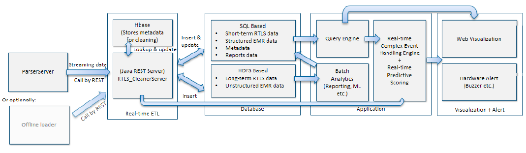
Figure 2 – Data flow
The components on the left side are the “sources” of the data inside our system. The parser server from the Real-time ETL component listens HTTP port for data packages from RTLS software. It translates the bytes package and sends the translated data entries into the cleaner server, which is another sub-component of the Real-time ETL component enriches and cleans the data according to the metadata store which is implemented in HBase. The cleaned data is then mirrored and sent to two data stores: a SQL based database and the Hadoop Distributed File System (HDFS). They are the data sources for the applications. In the applications, there are analytic components and the query engine, they run queries and analytics on top of the data in the data stores and store the result back to the data store or directly send the data to the visualization server in JSON. In addition, the cleaner server also generates event data. One copy of the data will be stored in the HDFS, another copy of the data will be directly sent to the rule engine.
Necessary Hardware
The main hardware needed for Pilots 9, 10 and 11 were the RTLS components.
Cable-free (wireless, battery operated) IR beacons are placed at the ceiling of rooms or hallway zones, where localization is needed. The beacons emit (invisible) IR light containing a unique code representative for the zone, that reflects from the walls, floor and ceiling of the room, thus “filling” the room with the coded IR light signal. The tags of this system detect this IR code as soon as they enter the room, and subsequently send this zone code, together with their own unique ID, wirelessly to one of the receivers. These act like access points of the system, and take care of transferring the information to the central server which collects and processes all events.
A broad array of tags is available for this system, including patient tags, asset tags and staff badges of different sizes and with different features and specifications. Versions are for example also available that cannot only be used in areas covered by IR beacons, but also in areas only covered by a WiFi localization system, for course localization in parts of the hospital where room level accuracy and certainty is not needed.
The type and amount of hardware needed for a setup depends not only on the type of setup chosen (Wifi vs IR only) but also on the vendor used.
Software Components
Only in Pilot 11 there is a user facing Software component. This is an asset management solution from Philips PerformanceFlow. This allows the users to search and identify the location of the tagged assets.